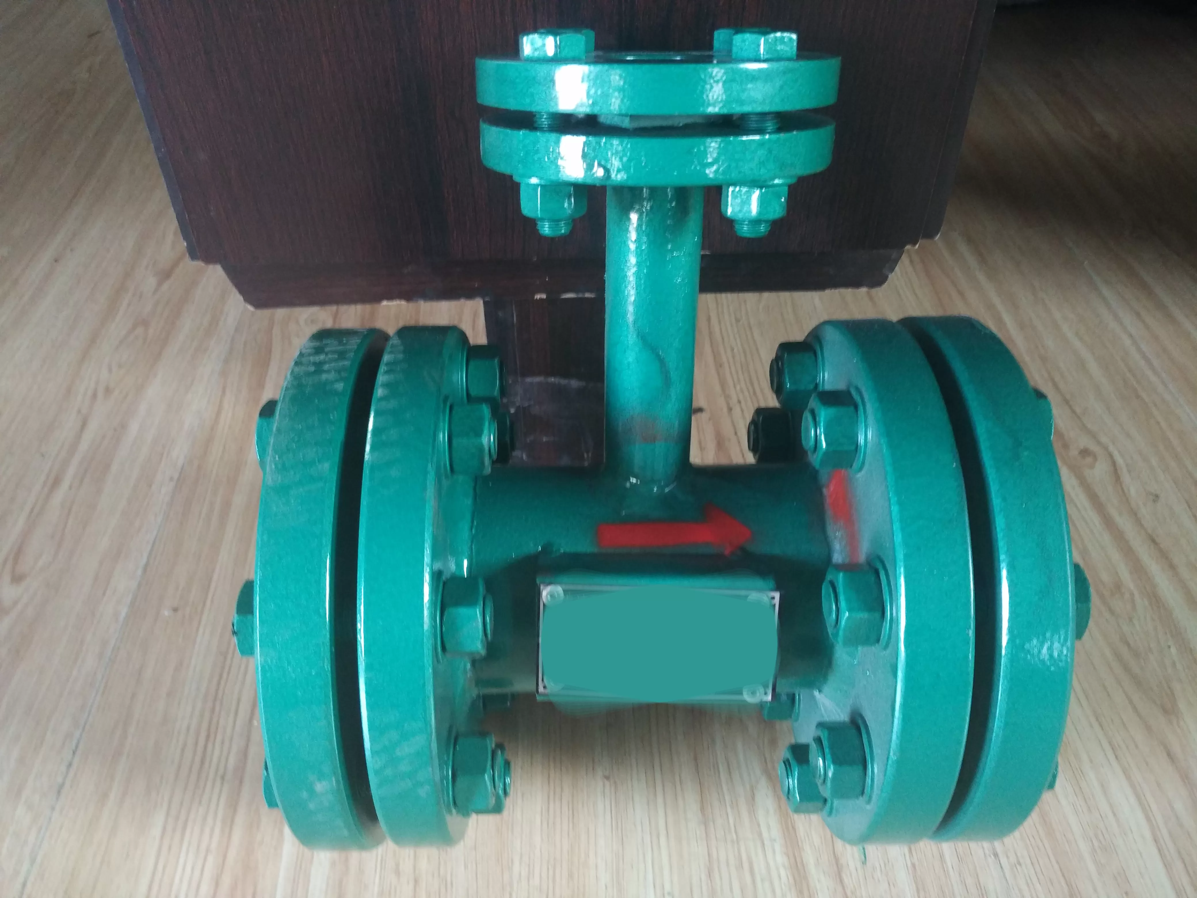
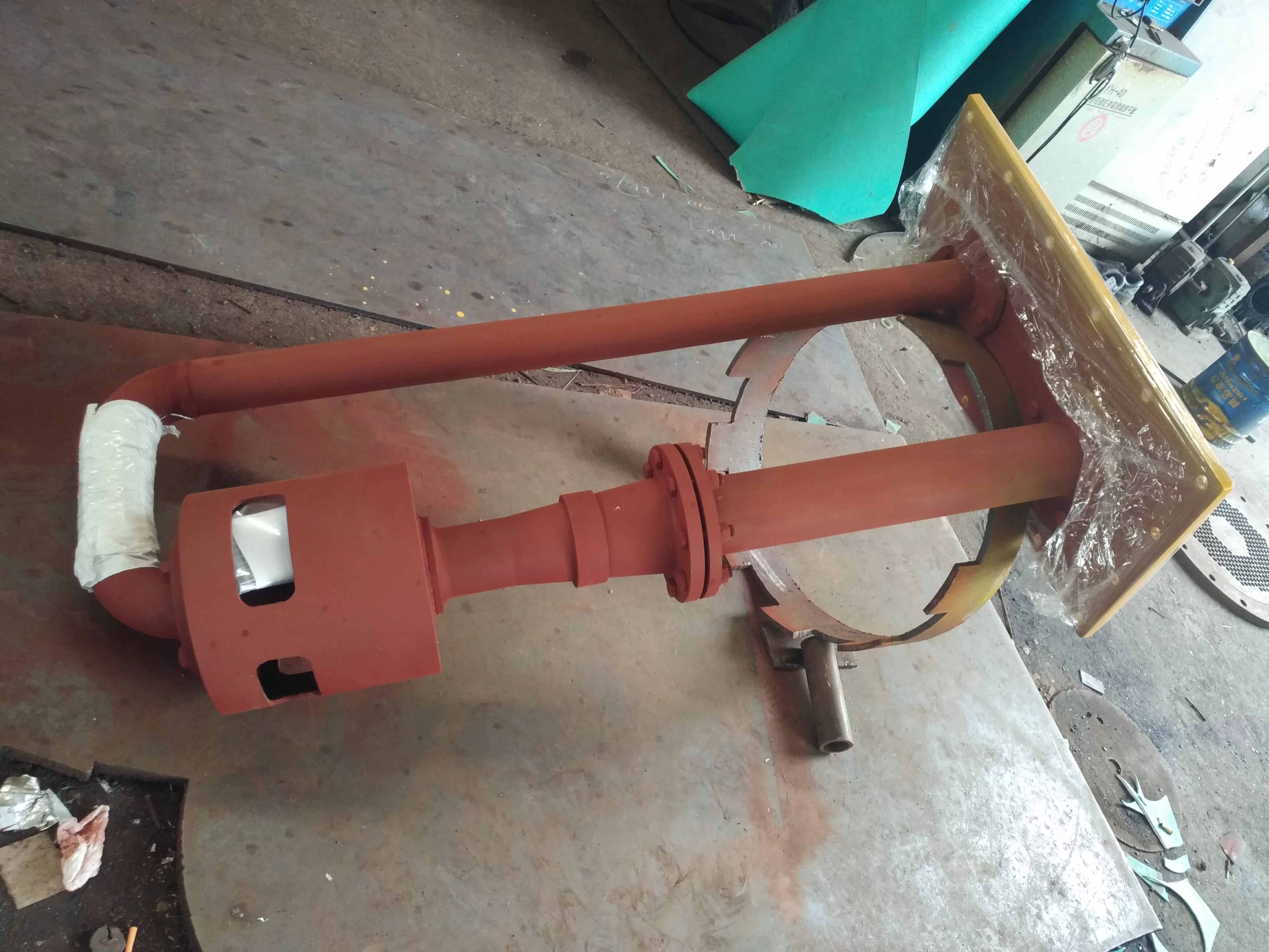
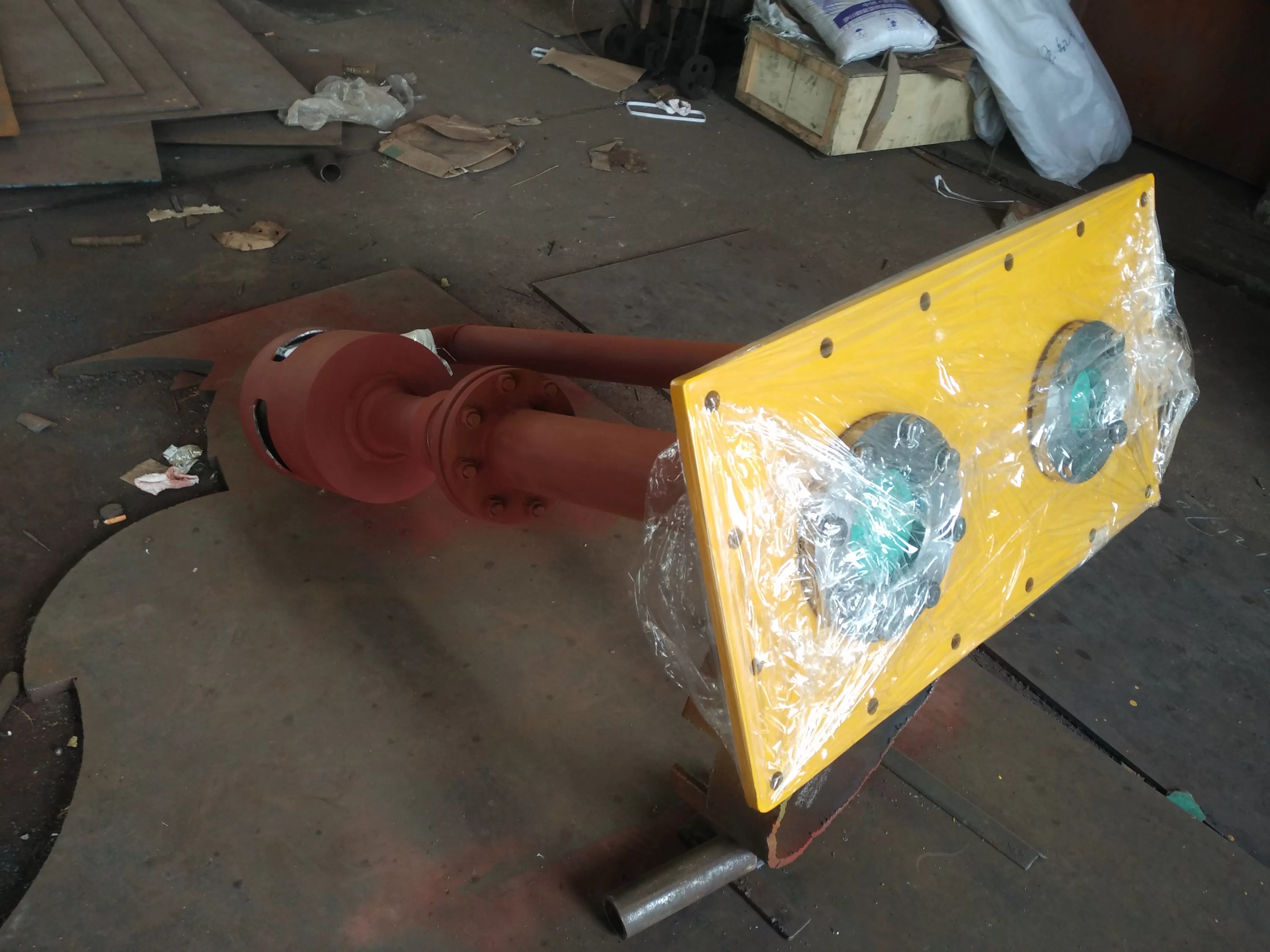
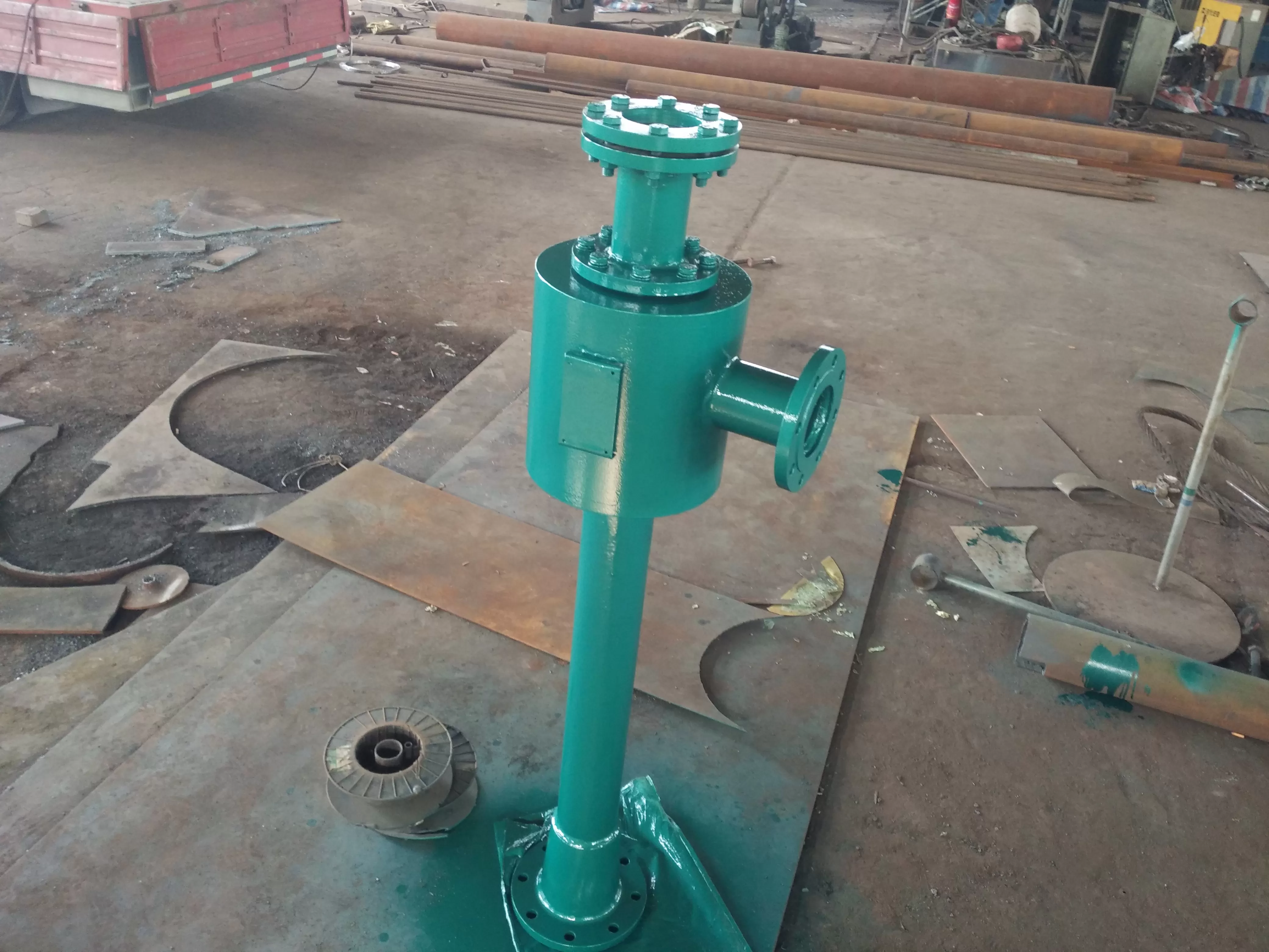
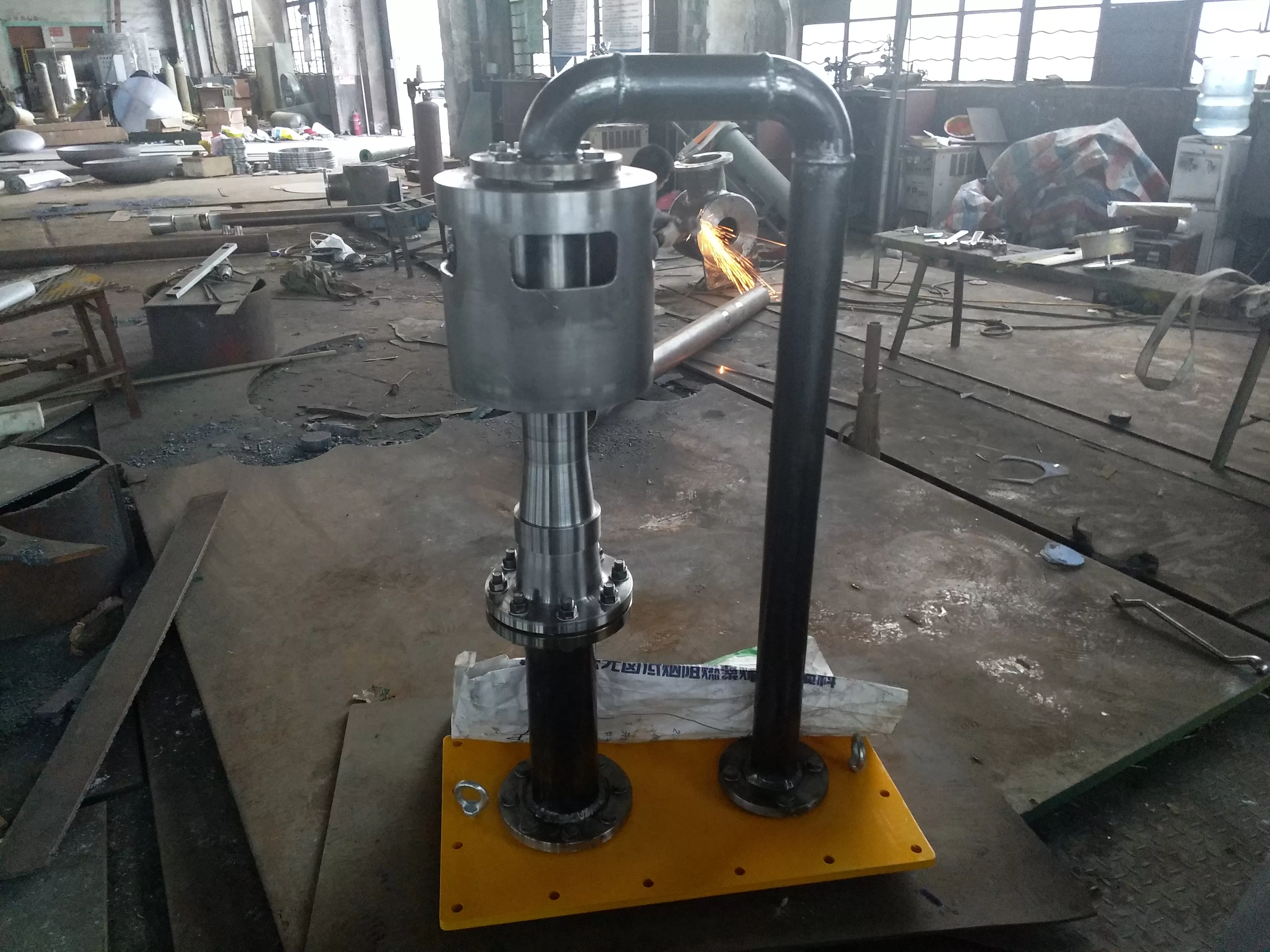
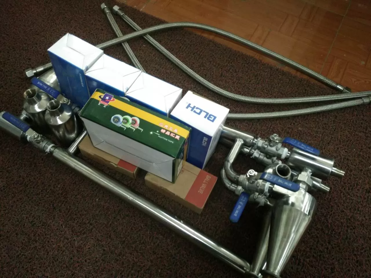
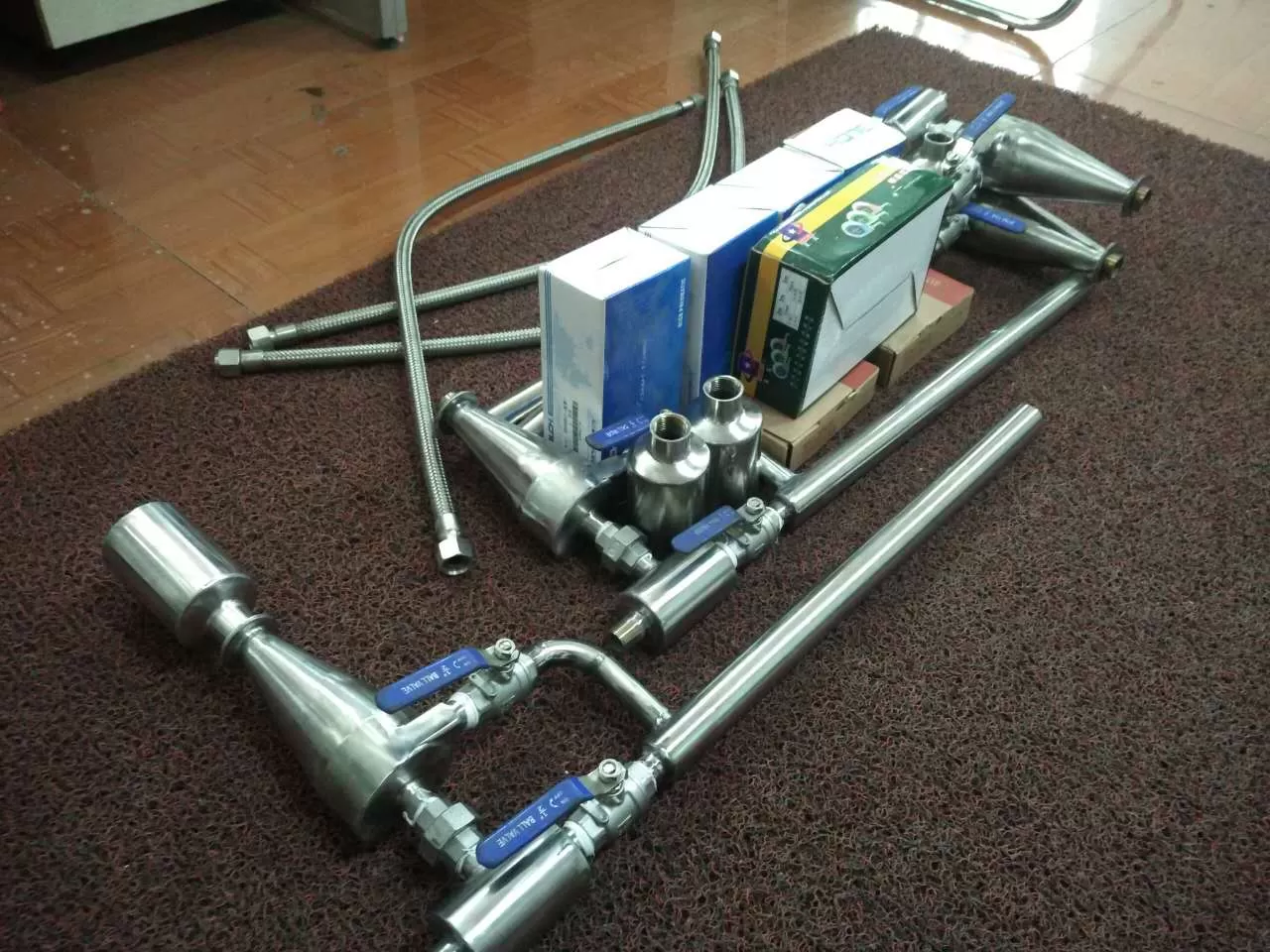
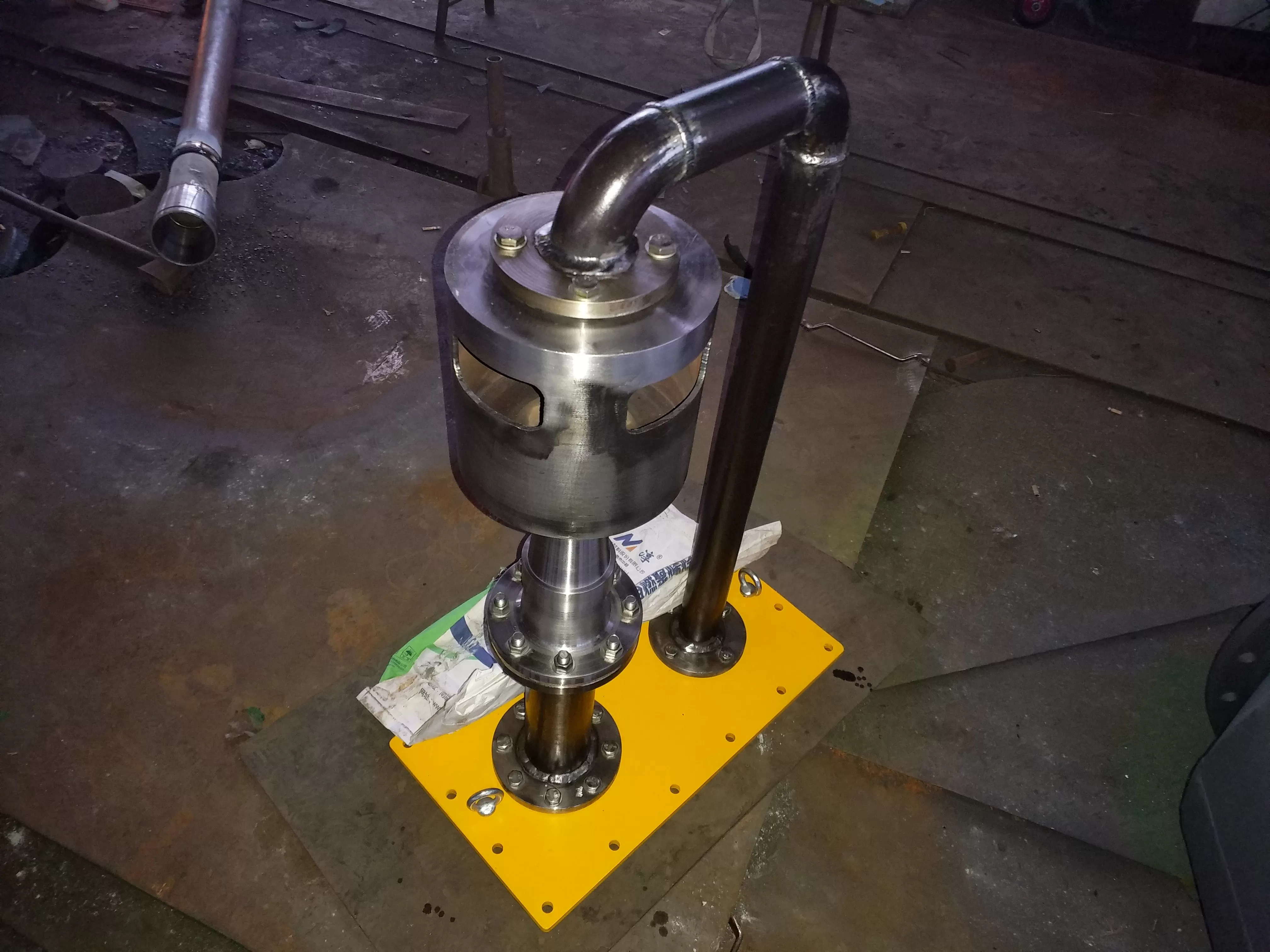
Application of Water Pump Vacuum Retainer
The water pump vacuum holder is suitable for various purposes of self suction (negative pressure suction) water pump devices and pump stations, water plant filter siphons, and other siphon guide pipes for vacuuming and maintaining vacuum. Reduce the interval between stopping and starting the pump, shorten the time, and start the non running pump for water supply
The ZBQ type water pump vacuum retainer is a derivative design of the WDF type, which overcomes the defect of exhaust steam easily returning to the pump body during WDF type air exchange, shortens the pumping time, and ensures that the water pump suction pipe forms a vacuum quickly; This device adopts the principle of water and gas displacement and uses the method of automatic drainage and air suction to achieve automatic formation and maintenance of vacuum for non self filling water pumps or siphons. It has the ability to supply multiple water pumps with one retainer at the same time, which is more reliable, convenient, and energy-saving than the traditional vacuum pump air suction and water suction method- The desire for automatic water intake through bottom valves in various types of suction pump devices and pump stations.
The vacuum retainer of the water pump operates automatically and requires manual operation; Work - only a small amount of tap water is needed (the used tap water can still flow back to the pool for further use) and a small amount of single-phase (220V) electricity. It is an energy-saving and microcomputer automated control equipment for water supply and drainage pump stations, filter siphons in water purification plants, and other siphon pipes for guiding water. At the same time, it is also a physical equipment for maintaining pump vacuum both inside and outside non self filling pump stations.
Installation and Use of Water Pump Vacuum Retainer:
1. The vacuum retainer of the water pump is located at the corner between the water pumps, and the replacement tank is placed on a steel bracket. The bracket surface should be 0.2-0.5 meters higher than the water pump surface and level to ensure a stable placement of the replacement tank. Then, connect the suction pipe, water pipe, drainage pipe, and other pipes and valves according to Figure 2.
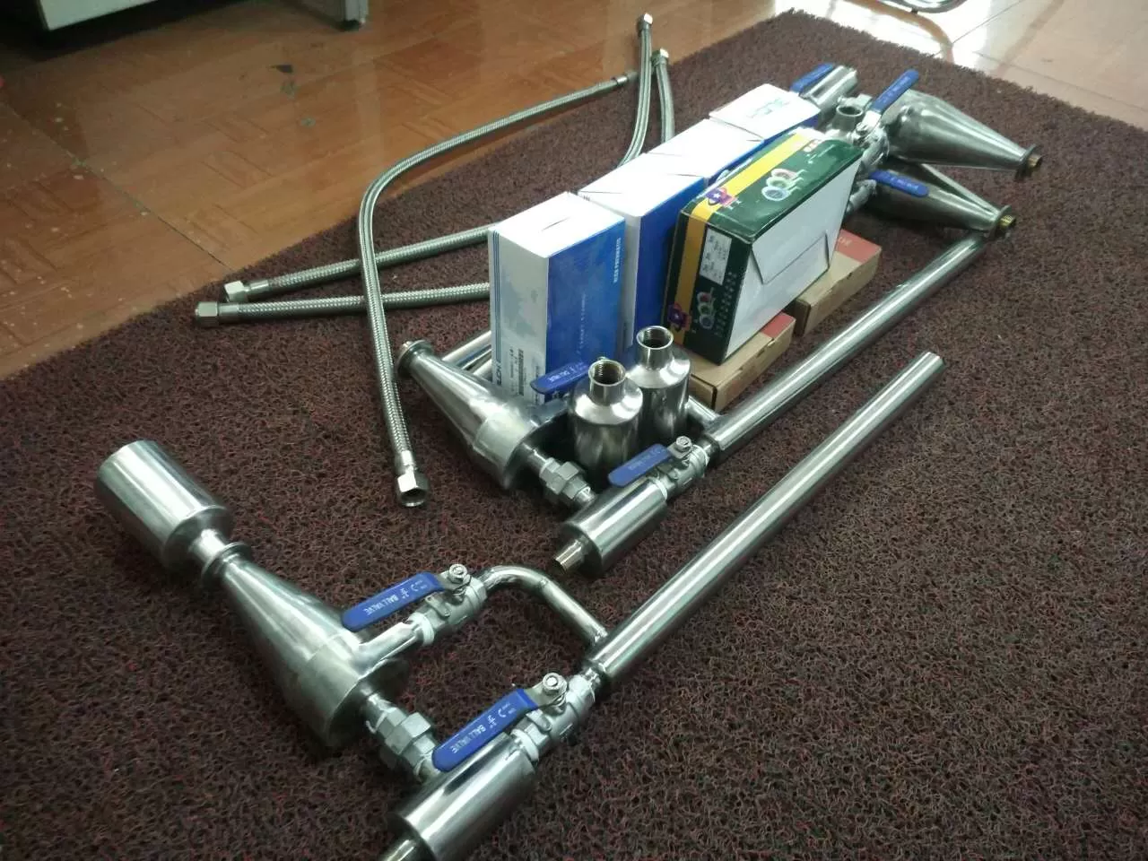
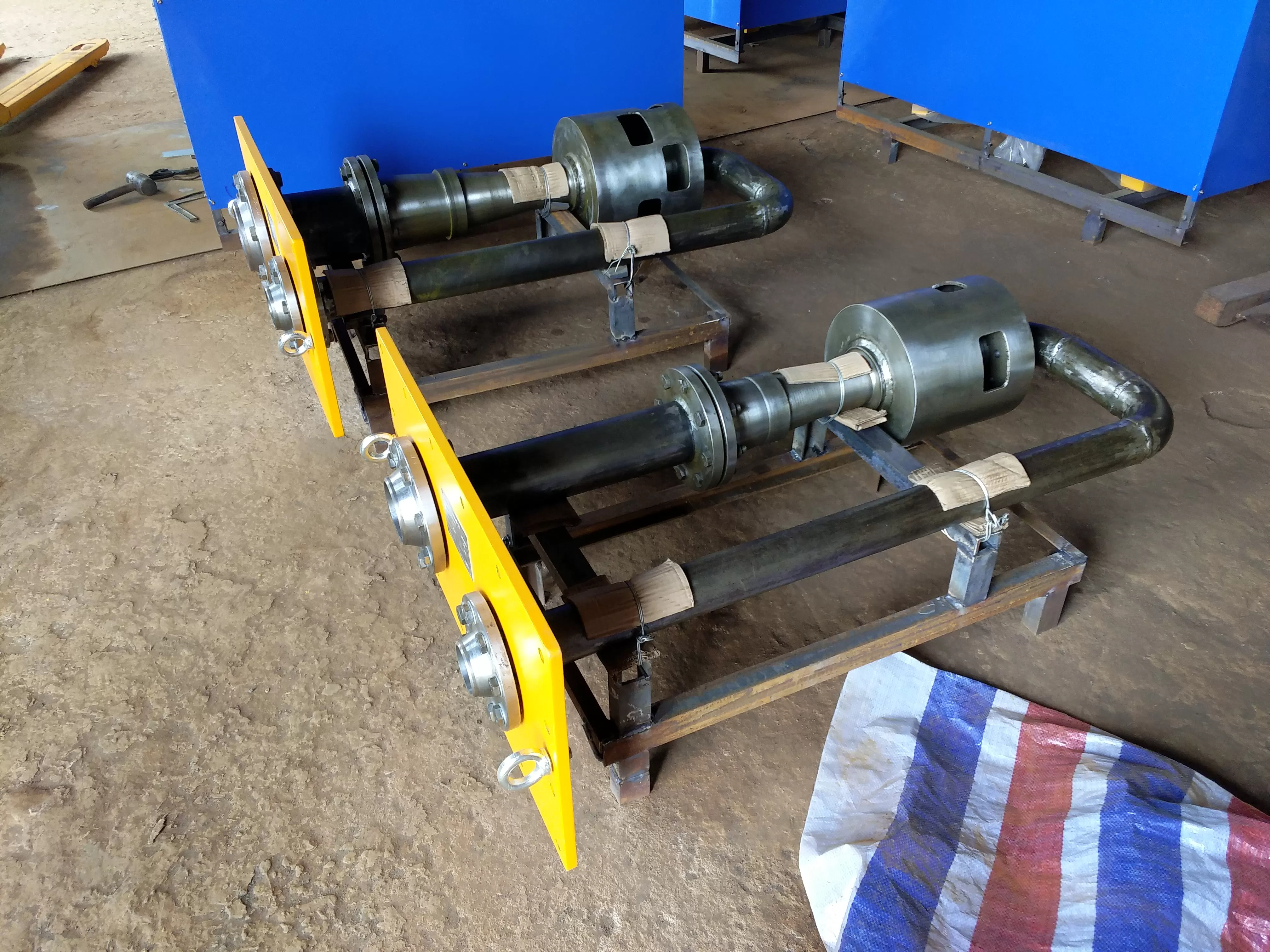
2. If the vacuum retainer of the water pump is in a component transportation state (see component diagram ①), it needs to be assembled and formed on site, and the method is as follows:
(1) Place the can body on the bracket, adjust the distance between the two cans, and install the lower loop (see Figure 2) without tightening it;
(2) Adjust the angle of the two displacement tanks in the installation loop to match the two active joints of the - loop (see Figure ③) and tighten them, then tighten the lower loop;
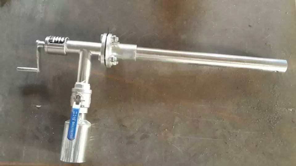
(3) Install the switch valve core (see Figure ④) and remove its transportation fixing pin;
(4) Formed after installing the water pipe (see Figure ⑤).
3. The drainage pipe of the vacuum retainer of the water pump should be connected to a suction tank or well through a single pipeline, and there should be no downhill slope towards the displacement tank. The diameter of the pipe should be 50mm, and the outlet should be at a low water level of 0.5 meters (if it is difficult to install a single pipeline, it can also be connected to the suction pipes of two water pumps nearby).
4. The suction pipeline connecting the water pump and the replacement tank should not have a downhill slope towards the replacement tank. The joints of various pipelines should ensure no air or water.
5. The gate valve installed in the water pump (see Figure 2) is usually placed in the open position and only closed when repairing the water pump.
6. The one-way water stop exhaust valve automatically closes when the water pump is started to supply water, and automatically opens when the water supply is stopped, without the need for human operation.
Manufacturer of Water Pump Vacuum Retainer
Water pump vacuum holder with instructions:
For the water pump system, a "one-way water stop exhaust valve" should be added to the exhaust pipe of the water pump, which is connected in series with the gate valve installed in the water pump (see Figure 2). This valve automatically closes when the water pump is started to prevent pressure water from entering the water gas replacement tank. When the water pump stops running, it automatically opens to allow the gas entering the water pump to rise to the replacement tank, which can keep the water pump in a vacuum state (this valve is manufactured by Lianyungang Lisheng Company).
7. For water pumps with a water seal ring, the water seal pipe should be connected to the tap water to ensure that the water seal is in place inside the pump packing.
8. After installation, check if there is any water or gas in the pipeline, and if so, inject water into the replacement tank for use.
9. The water pump or siphon creates and maintains a vacuum (see Figure 2)
(1) Connect the water -, open the water pipe switch valve (2) and manual water injection valve (1) on both tanks, and start injecting water into both tanks simultaneously. When the water is full and there is a slight overflow, close the manual water injection valve (1), and the water injection work will begin.
(2) Place the gate valve on the suction pipe of the water pump in the open position.
(3) Place the manual intake valves (3) on each replacement tank in the open position.
(4) - Open the manual water outlet valve (4) on a certain displacement tank, and the tank will begin water and gas exchange work.
(5) After an interval of about - minutes, open the manual valve (4) on the other replacement tank. At this point, the opened or closed manual valve will be immediately fixed, and future water injection and water gas replacement work will be automatically carried out.
Water pump vacuum holder - output potential:
The vacuum retainer of the water pump adopts the principle of water and gas displacement and uses the method of drainage, air extraction, and water diversion to automatically form and maintain the vacuum of non self filling water pumps or siphons. Has the ability to supply vacuum retainers for multiple water pumps simultaneously.
This product operates automatically and does not require human operation or electricity. It only requires a small amount of tap water for operation (the used tap water can still flow back to the water tank for continued use). It is an energy-saving and microcomputer automated control equipment for water supply and drainage pump stations, filter siphons in water purification plants, and other siphon pipes for guiding water.
Construction and Working Principle of Water Pump Vacuum Retainer
1. Pump Vacuum Retainer - Manufacturing
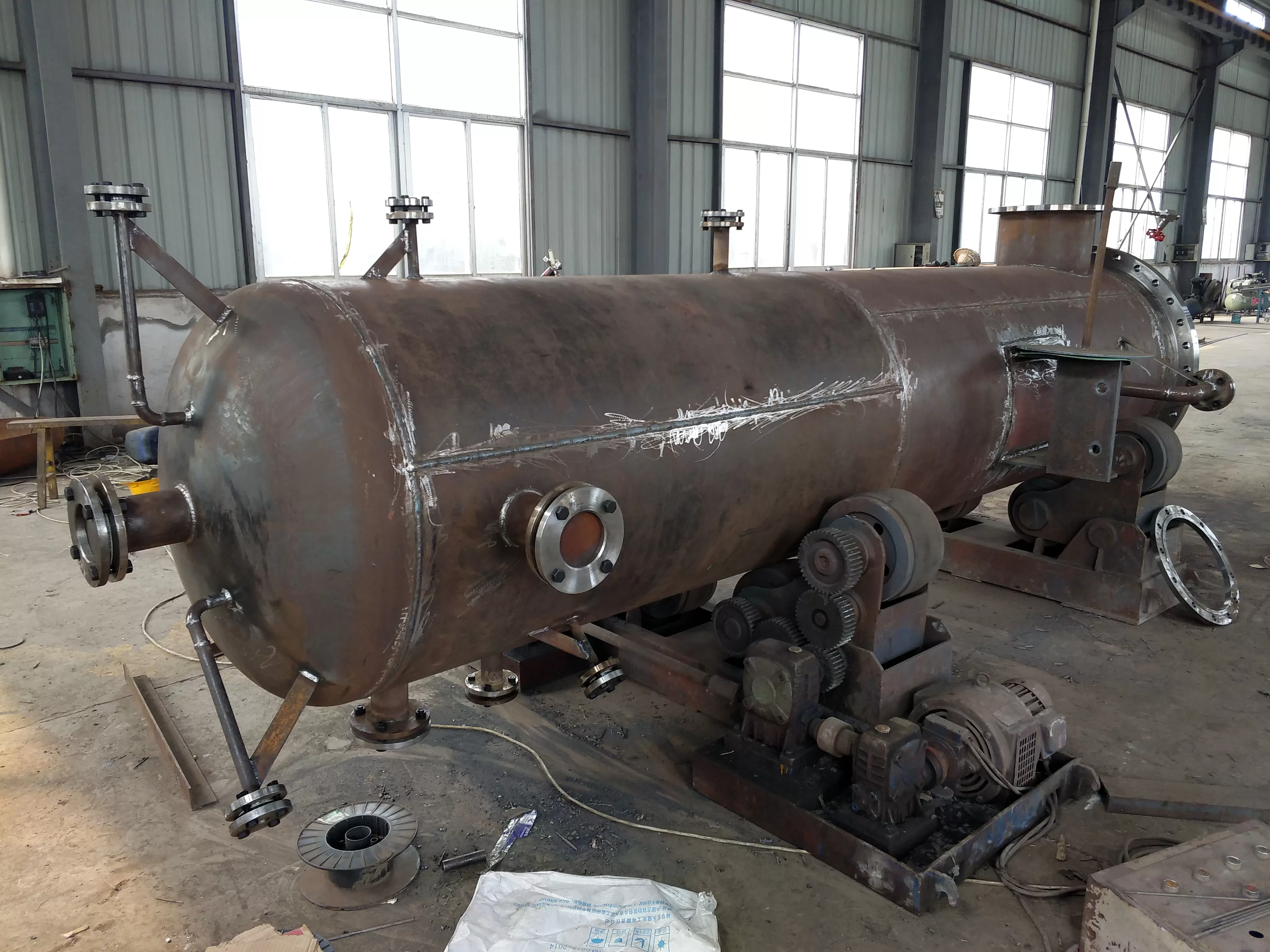
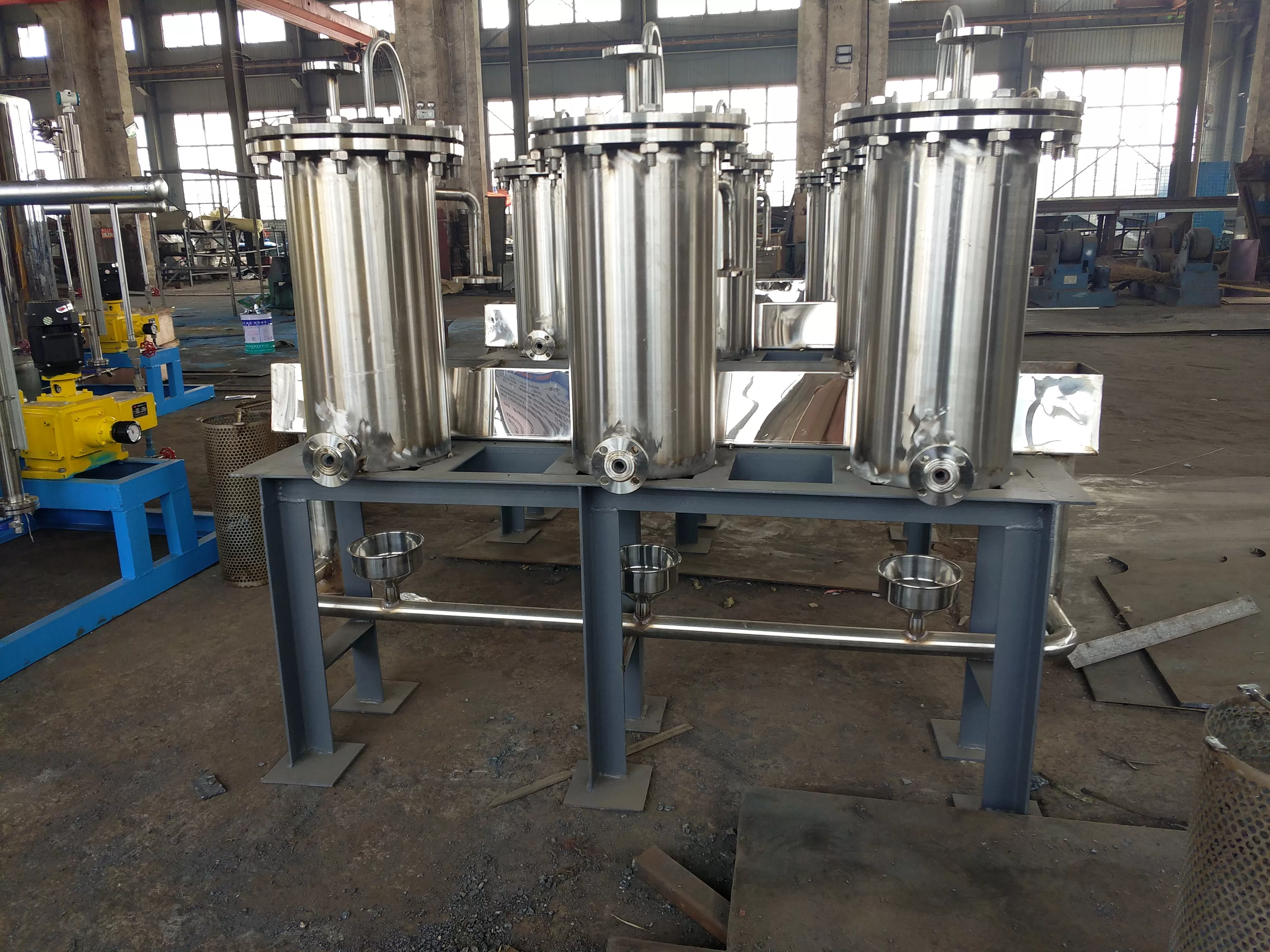
The vacuum retainer of the water pump consists of three parts: a water and gas displacement tank, a water injection and exhaust system, a drainage system, and a drainage and suction system, as shown in the figure.
(1) Water and gas replacement tank
It is a sealed tank that stores water for replacement and inhaled gases. The tank is equipped with a water level float, a water stop float, and a water stop float limit tank. This product adopts a dual tank structure, which can maintain ventilation during operation and serve as a backup for each other during maintenance.
(2) Water injection and exhaust system-
It consists of manual water injection valve, water injection valve, water injection switch valve, water injection pipe, and exhaust valve.
(3) Exhaust and suction system-
It consists of a sealing head, a drainage outlet, a drainage pipe, a manual drainage valve, as well as an intake pipe, an intake valve, etc.
2. Working principle of water pump vacuum retainer
When the water pump vacuum holder opens the injection valve, tap water is injected into the tank. The water level in the tank continuously rises, and the gas inside the tank is under pressure. The exhaust valve of the tank is automatically opened to discharge the gas inside the tank. When the water level in the tank rises to the specified height, use the water level float and stop float to operate the water injection switch valve, automatically close the water injection valve, and stop water injection. At the same time, open the water stop float valve, and under the action of force, the water in the tank is discharged through the drainage pipe, forming a vacuum inside the tank. The water pump that needs to be evacuated and the air in its suction pipe (or siphon pipe) are sucked into the displacement tank through the suction pipe, intake valve, and suction. When the water level in the tank drops to the specified height, due to the action of the water level float and the water stop float, under the suction force in the drainage pipe, the water stop float valve closes the drainage outlet and stops draining. At the same time as stopping drainage, the water injection switch valve is operated by the water stop float limit pipe to open the water injection valve and start water injection. Afterwards, the system enters the cycle process, filling it with water and maintaining a vacuum state.
Water pump vacuum retainer - different specifications can be arranged according to user needs for separate design schemes! Interested parties contact us!
Selection of Vacuum Retainer for Water Pump:
-The vacuum retainer of each water pump can simultaneously maintain the vacuum of 4-6 water pumps. When maintaining vacuum, the product is related to the model and size of the water pump; The duration of vacuum formation is related to the volume and suction head of the suction pipe and water pump. The product model and parameters are as follows:
Production model and parameters of water pump vacuum retainer:
| 水泵真空保持器型號 | ZBQ-1 | ZBQ-2 | ZBQ-3 |
| 規(guī) 格 | ?600x1200x2 | ?750x1300x2 | ?900x1450x2 |
| 容 積(m3) | 1.0 | 1.2 | 2.0 |
| 抽氣量(m3) | 0.85/5min | 0.90/5min | 0.95/5min |
規(guī) 格
容 積(m3) | ?600x1200x2 | ?750x1300x2 |
| 1.0 | 1.2 |
水泵真空保持器合理的選型見下表:
| 水泵真空保持器吸水管直徑mm | <300 | 350 | 400 | 450 | 500 | 600 | 700 | 800 |
| 吸水管長度L(m) | ZBQ-1型 | L<17 | L<12 | L<10 | L<8 | L<6 |
|
|
|
| ZBQ-2型 |
|
| L<14 | L<11 | L<9 | L<6 |
|
|
| ZBQ-3型 |
|
|
| L<16 | L<12 | L<10 | L<8 | L<6 |
Explanation of the diagram for the vacuum retainer of the water pump:
1. The number of water pumps that need to maintain vacuum can be increased by more than 6, and those with less than 3 or lower water supply retention requirements can be reduced;
2. When using the filter siphon to vacuum, choose WDF-96C type;
3. When the length and diameter of the suction pipe are greater than the values listed in the table, only a slightly longer vacuum time is formed, which has no effect on maintaining the vacuum.
Attention: The above technical specifications and parameters of the vacuum holder are for reference only and are mainly based on international design.
